
Every smart home system, commercial AV setup, and security network we install at Treasure Valley Solutions depends on one thing working flawlessly beneath the surface: the cabling. A well-executed str...
Structured Cabling System Design: Standards & Best Practice
Every smart home system, commercial AV setup, and security network we install at Treasure Valley Solutions depends on one thing working flawlessly beneath the surface: the cabling. A well-executed structured cabling system design is the foundation that determines whether your technology performs reliably for years, or becomes a frustrating tangle of workarounds and service calls. After more than a decade of designing and installing integrated technology systems across homes and businesses in Idaho's Treasure Valley, we've seen firsthand how proper cabling infrastructure separates a great installation from a costly headache.
Structured cabling isn't just about running wires from point A to point B. It's a standards-driven approach to building a telecommunications backbone that supports current needs and scales cleanly as technology evolves. Whether you're a homeowner planning a new build, a commercial builder coordinating trades, or a business owner upgrading your facility, understanding these standards and best practices puts you in a much stronger position to make informed decisions before walls close up and options disappear.
This guide breaks down the core principles of structured cabling system design, from the recognized standards (TIA/EIA) that govern how it's done, to the practical choices around cable types, pathway planning, and documentation. We'll walk through how each subsystem works together, cover common mistakes that drive up costs, and share the best practices we apply on our own projects every day. By the end, you'll have a clear, working understanding of what goes into a professional cabling infrastructure and what to expect when it's time to plan yours.
What a structured cabling system is and what it includes
A structured cabling system is a standardized, organized approach to building a complete telecommunications infrastructure inside a home or commercial facility. Rather than running individual cables for each specific device or application, structured cabling creates a unified physical layer that carries voice, data, video, and control signals across a single, well-planned network. This approach gives you a system that is easier to manage, simpler to troubleshoot, and built to handle technology changes without requiring a full re-wire every few years.
Think of it as the nervous system of your building. Every smart device, access point, security camera, AV component, and workstation connects back to this infrastructure. Good structured cabling system design means every signal travels a clean, reliable path from source to destination, and every future technology upgrade has a place to plug into without disrupting what's already working.
A structured cabling system doesn't serve a single application; it serves every application running in your building today and the ones you'll add tomorrow.
The six subsystems that make up the infrastructure
Structured cabling is not a single run of wire. It's a framework built from six defined subsystems, and each one plays a specific role in how the system functions as a whole.
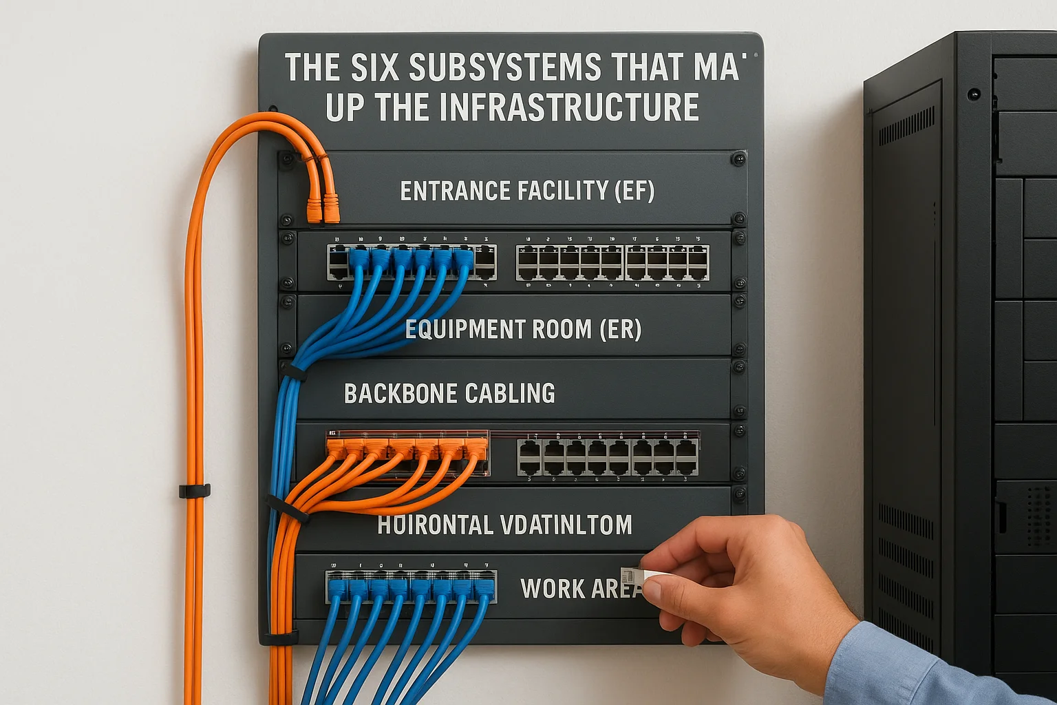
| Subsystem | Function |
|---|---|
| Entrance Facility (EF) | Where outside services (internet, phone, fiber) connect to your building's internal network |
| Equipment Room (ER) | Houses main switching, routing, and server equipment for the entire facility |
| Backbone Cabling | Connects equipment rooms to telecommunications rooms across floors or buildings |
| Telecommunications Room (TR) | Intermediate distribution point serving a floor or zone |
| Horizontal Cabling | Runs from the TR to each individual work area or device outlet |
| Work Area (WA) | The endpoint: the wall plate, patch cord, and connected device at each location |
Each subsystem has defined distance limits, hardware requirements, and performance standards that govern how it must be installed. Skipping or combining subsystems is one of the most common ways a cabling project ends up failing a performance test or causing network problems after move-in. Your installer needs to treat each subsystem as its own engineered component, not a suggestion.
What types of signals and systems it carries
One of the biggest practical advantages of structured cabling is that a single, well-designed infrastructure supports many different systems at once. You don't need separate, incompatible wiring plants for your data network, your phone system, your access control, and your audio-video distribution.
Here is what a properly designed structured cabling system typically carries across a residential or commercial facility:
- Data and internet: Ethernet connections to workstations, wireless access points, smart TVs, and IoT devices
- Voice: VoIP phone systems and traditional analog lines
- Security and access control: IP cameras, card readers, door controllers, and intercom systems
- Audio and video distribution: Whole-home audio, digital signage, and conference room AV
- Building automation: Smart lighting controls, HVAC sensors, and energy management systems
Your cabling plant carries all of these signals reliably when it's designed and installed to the correct standards. When it's not, you spend time chasing interference problems, dropped connections, and capacity limits that no amount of upgraded equipment can fix on its own. Getting the infrastructure right the first time is always less expensive than correcting it after walls are closed and finishes are complete.
The standards and codes that shape your design
When you start planning a cabling infrastructure, standards aren't optional reading. The Telecommunications Industry Association (TIA) and Electronic Industries Alliance (EIA) publish the primary standards that define how structured cabling systems must be designed and installed in North America. These documents specify everything from cable performance categories to maximum horizontal run distances, and following them is what separates a system that passes certification testing from one that creates problems after the job is done.
Designing to standard isn't about compliance paperwork; it protects your investment by ensuring every component in the system is compatible, testable, and upgradeable.
The core TIA/EIA standards you need to know
The TIA-568 series is the foundation for most commercial and residential structured cabling system design decisions. TIA-568.0 covers general requirements, TIA-568.1 outlines commercial building cabling, and TIA-568.2 addresses balanced twisted-pair cabling components including category specifications. TIA-569 governs pathways and spaces, telling you how to size conduit, cable trays, and equipment rooms. TIA-606 covers the administration standard that defines how you label and document your infrastructure. Knowing which standard applies to each decision helps you ask better questions and evaluate contractor work more accurately.
| Standard | What it governs |
|---|---|
| TIA-568.1 | Commercial building telecommunications cabling |
| TIA-568.2 | Balanced twisted-pair cabling components and categories |
| TIA-569 | Pathways, spaces, conduit, and equipment room sizing |
| TIA-606 | Administration, labeling, and documentation |
| TIA-607 | Grounding and bonding for telecommunications systems |
Local codes and the National Electrical Code
Beyond TIA standards, your installation must comply with the National Electrical Code (NEC), specifically Article 800 for communications circuits and Article 725 for Class 2 and Class 3 wiring. Local jurisdictions in Idaho follow the NEC but sometimes adopt local amendments, so always confirm current requirements with your local authority having jurisdiction (AHJ) before finalizing your design. Fire-rated spaces and plenum areas add another layer of requirements, since plenum-rated cable (CMP) is required wherever cabling runs through air-handling spaces. Skipping this step can result in failed inspections or, worse, a serious safety hazard.
Selecting the correct plenum or riser-rated cable for each section of your building isn't just a code requirement; it directly affects fire safety performance and your insurance coverage if something goes wrong. Always confirm the cable jacket rating before purchasing materials, not after the wire is already pulled through the ceiling.
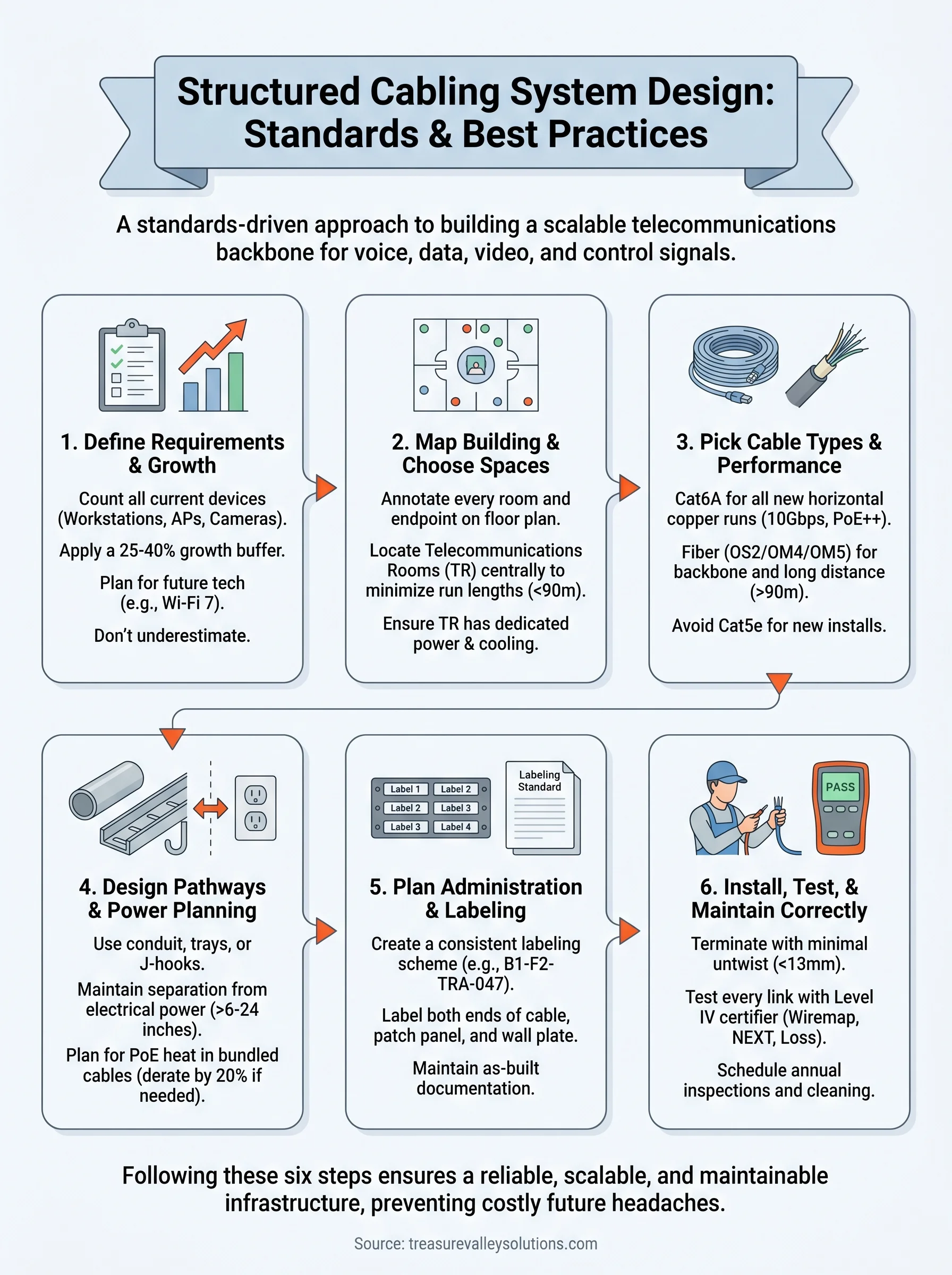
Step 1. Define requirements and growth targets
Before you touch a cable or draw a single line on a floor plan, you need a clear picture of what the infrastructure must support today and what it needs to handle three to five years from now. Skipping this step is the most expensive mistake you can make in a structured cabling system design project, because adding capacity after walls are closed costs four to six times more than building it in upfront.
Plan for the technology you expect to add, not just the technology you're installing today.
Gather current usage data
Start by counting every active device and connection point your facility currently uses or will need at occupancy. Include workstations, IP phones, wireless access points, IP cameras, smart displays, AV endpoints, building automation controllers, and any other networked device. Don't estimate this number; walk the space and document it room by room before committing anything to a drawing.
Use this template as a starting point for each room or zone, then fill it in for every space in the building before moving to pathway planning:
| Location | Device Type | Connection Type | Quantity | Notes |
|---|---|---|---|---|
| Conference Room A | Workstation | Cat6A Ethernet | 4 | One per seat |
| Conference Room A | Wireless AP | Cat6A Ethernet | 1 | Ceiling mount |
| Conference Room A | IP Camera | Cat6A Ethernet | 1 | Corner mount |
| Lobby | Digital Signage | Cat6A Ethernet | 1 | Wall mount |
| Server Room | Network Switch | Fiber + Copper | 2 | Main distribution |
Set a growth window and plan for expansion
Once you have your current device count, apply a 25 to 40 percent expansion buffer to every zone. This accounts for headcount growth, new technology deployments, and changes in how spaces are used. A 10-person office that expects to grow to 15 people in three years needs cable runs and port counts sized for the larger number from day one, not retrofitted later.
Factor in technology trends specific to your building type when finalizing your growth targets. Commercial spaces should plan for higher wireless access point density as Wi-Fi 7 deployments expand across more facilities. Residential new builds should account for additional home automation and streaming endpoints in every room, including outdoor spaces and garages that frequently get overlooked during early planning conversations.
Step 2. Map the building and choose key spaces
Once you have your device counts and growth targets from Step 1, the next task is translating that data onto an actual building layout. Floor plan mapping is where your structured cabling system design becomes a physical document that every trade on the job can reference, coordinate against, and build from. Start with an accurate architectural floor plan in PDF or CAD format, and if one doesn't exist, measure the building yourself and create a rough-scale drawing before going any further.
A floor plan without cable run annotations is just a picture; your drawings need to show every cable path from the work area back to the telecommunications room.
Annotate every room and endpoint location
Work through each room systematically and mark the exact location of every outlet, access point, camera, and device you documented in Step 1. Use a simple color-coding system to distinguish cable types or system categories at a glance. For example, blue dots for data outlets, red for IP cameras, and green for wireless access points. Consistent annotation makes it immediately obvious if a zone is under-served before a single cable is pulled.
After marking all endpoints, draw preliminary cable routes from each endpoint back toward the nearest telecommunications room. This step reveals long horizontal runs that may exceed the 90-meter permanent link limit defined in TIA-568.1, forcing you to either add a telecommunications room or reconsider your layout before construction begins.
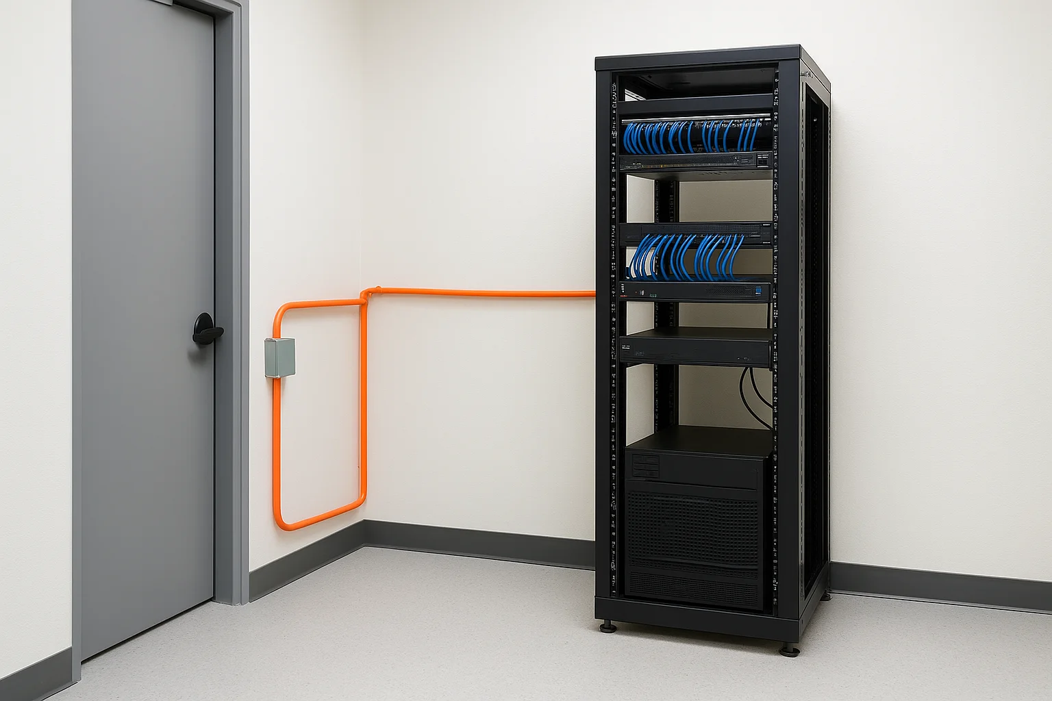
Identify and size your telecommunications rooms
Every floor or zone covering more than roughly 1,000 square meters typically requires its own telecommunications room (TR) to keep horizontal runs within distance limits. Choose a location near the geometric center of each zone it serves, away from electrical panels, motors, and other sources of electromagnetic interference. TRs need dedicated power circuits, proper ventilation, and enough wall space for a full-height rack or wall-mounted cabinet.
Use this checklist when evaluating each candidate TR location:
- Minimum room size: 3m x 2.4m for most commercial installations
- Access to building backbone pathways (conduit or cable tray)
- No plumbing or HVAC equipment sharing the same room
- Dedicated 20-amp circuits for equipment
- Ambient temperature maintained between 18°C and 27°C
Locking down these locations early in your design prevents costly relocations once framing and mechanical work are already underway.
Step 3. Pick cable types and performance categories
Choosing the right cable type for each part of your infrastructure is one of the most consequential decisions in any structured cabling system design project. Select a category that's too low and you'll hit performance ceilings before the system is five years old. Select the wrong jacket rating and you'll fail inspection. Every cable choice should be driven by the distance, bandwidth, and environment requirements of that specific run, not by what happened to be on sale or what a supplier recommended without reviewing your drawings.
Copper cable categories and when to use each
Cat6A is the current recommended baseline for all new horizontal copper runs in both commercial and residential installations. It supports 10 Gbps over the full 90-meter permanent link, handles Power over Ethernet (PoE++) without the heat buildup that causes signal degradation in bundled Cat6 runs, and is backward compatible with every lower category device you connect to it. Cat6 remains acceptable for low-density residential projects with short runs and no high-power PoE requirements, but it's no longer the right default choice for a facility you expect to operate for a decade.
Never specify Cat5e for new construction; the marginal cost savings disappear quickly when you need to re-pull cable to support technologies that are already in wide deployment.
Use this table to match cable category to application during your planning phase:
| Category | Max Speed | Max Distance | Best Application |
|---|---|---|---|
| Cat5e | 1 Gbps | 90m | Legacy upgrades only |
| Cat6 | 10 Gbps | 55m at 10G | Low-density residential |
| Cat6A | 10 Gbps | 90m | All new commercial and residential runs |
| Cat8 | 25/40 Gbps | 30m | Data center switch-to-switch only |
When to use fiber optic cable
Fiber is the correct choice for backbone runs between your equipment room and telecommunications rooms, and for any horizontal run that exceeds the 90-meter copper limit. Single-mode fiber (OS2) works best for long inter-building runs, while multimode fiber (OM4 or OM5) handles most intra-building backbone distances at a lower hardware cost. Fiber is also the right call for runs that pass through areas with high electromagnetic interference, such as industrial spaces, mechanical rooms, or any path that runs parallel to large electrical equipment for extended distances.
Step 4. Design pathways, separation, and power planning
With your floor plan annotated and cable types selected, the next task in your structured cabling system design is mapping out how cables physically travel through the building. Pathway planning determines whether your installation looks clean and professional or turns into a disorganized mess that's nearly impossible to maintain. Every cable run needs a defined, protected path from the work area back to the telecommunications room, and that path needs to be designed before construction begins, not improvised during the pull.
Plan conduit and cable tray routing
Horizontal cable runs from the TR to each work area typically travel through one of three pathway types: conduit, cable tray, or J-hooks attached to the building structure. Conduit offers the strongest physical protection and makes future re-pulls straightforward, but it costs more to install. Cable tray works well in open ceilings above commercial spaces where you need to route large numbers of cables across long distances in a single organized run. J-hooks serve well in finished residential spaces where conduit isn't practical in every wall cavity.
Size your conduit and tray for at least 40 percent fill capacity at installation, leaving the remaining 60 percent open for future cable additions. A 1-inch conduit filled to capacity on day one forces you to core a new hole through a finished wall the next time you add a run. Always install conduit in a straight path with sweep elbows rather than sharp 90-degree turns, which would exceed the cable's minimum bend radius and degrade signal performance.
Maintain separation from electrical systems
Telecommunications cabling and electrical power wiring must never share the same conduit or run parallel to each other within six inches unless you use shielded cable or physical barriers. Electromagnetic interference from 120V or 240V circuits degrades signal quality on unshielded twisted-pair cable, and the closer the parallel run, the worse the effect.
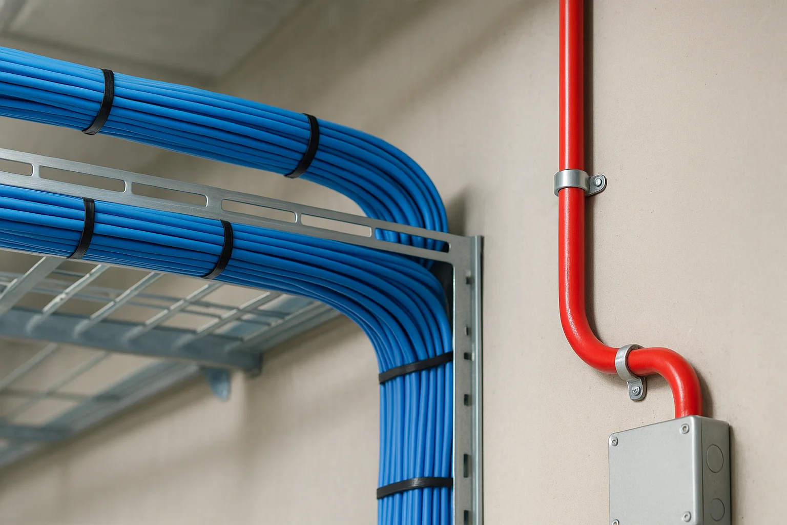
Separation is not optional; a single long parallel run next to a 20-amp circuit can cause enough interference to push a Cat6A link below its rated performance threshold.
Follow these minimum separation distances as a baseline for your pathway drawings:
| Condition | Minimum Separation |
|---|---|
| Unshielded telecom cable near power conduit | 6 inches |
| Telecom cable near fluorescent lighting ballasts | 12 inches |
| Telecom cable near motors or transformers | 24 inches |
Account for PoE power loads
Power over Ethernet devices like wireless access points, IP cameras, and VoIP phones draw power directly through your copper horizontal cables, which generates heat in bundled cable runs. A single Cat6A cable handles PoE heat easily in isolation, but 50 cables bundled tightly together in a tray can raise temperatures enough to reduce performance and shorten cable lifespan. Derate your cable's rated performance by 20 percent when bundles exceed 24 cables, and plan your conduit fill accordingly to keep temperatures within acceptable limits.
Step 5. Plan administration, labeling, and documentation
Administration is the part of structured cabling system design that most installers rush or skip entirely, and it's the reason experienced technicians can troubleshoot a system in minutes while others spend hours chasing unlabeled cables through a packed cable tray. A complete labeling and documentation standard needs to be defined before you pull a single run, not added as an afterthought once the installation is finished.
Build a consistent labeling system
Every cable in your infrastructure needs a unique, human-readable identifier that follows a consistent format across the entire building. TIA-606 defines the administration standard for telecommunications infrastructure, and it gives you a clear framework to base your naming convention on. A well-structured label connects the work area outlet back to its patch panel port, so anyone picking up a cable at either end knows immediately where it terminates.
A label that falls off or fades within two years is no better than no label at all; use heat-shrink printed labels on every cable end and engraved or printed labels on every patch panel port.
Use this label format template as a starting point for your horizontal runs:
| Label Component | Example | Purpose |
|---|---|---|
| Building code | B1 | Identifies the building in a multi-building campus |
| Floor number | F2 | Identifies the floor or zone |
| TR identifier | TR-A | Identifies the telecommunications room serving this run |
| Port sequence number | 047 | Unique sequential number for this outlet |
| Full label | B1-F2-TRA-047 | Complete identifier printed on both ends of the cable |
Apply the same identifier to the patch panel port and the wall plate, so the label on the cable matches what you see at both termination points without any translation required.
Create and maintain your documentation package
Your documentation package needs to include three core documents: an as-built floor plan showing every cable route and outlet location, a port schedule listing every cable identifier with its origin and destination, and an equipment inventory for each telecommunications room. Store these documents in both printed and digital formats, with the digital version kept in a cloud folder accessible to your facilities team.
Update your documentation every time you add, move, or remove a cable run. A documentation package that reflects the original installation but not the current state of the building is actively misleading and will cost you time on every future service call or upgrade project.
Step 6. Install, terminate, test, and maintain correctly
Every decision you made in your structured cabling system design process only produces results if the physical installation is executed with the same level of care. Poor termination technique, skipped testing, and no maintenance plan undo every standard and best practice you followed in the planning phase. Pulling cable correctly, terminating it cleanly, and certifying every link before occupancy are non-negotiable steps, not optional finishing touches.
Terminate cables correctly at every connection point
Termination quality determines whether your cable performs to its rated category or falls short of it. Maintain the cable's twist rate as close to the termination point as possible, untwisting no more than 13mm of pair at each jack or patch panel port. Exceeding this distance introduces crosstalk that no amount of equipment can compensate for. Use a 110-style punch-down tool with a cut blade on every termination, and follow the T568B wiring standard consistently across every outlet in the building unless your project specifically requires T568A.
A single poorly terminated jack can degrade an entire link's performance below its rated category, even if every other component in the run is installed perfectly.
Apply consistent wire management inside every patch panel and telecommunications room. Velcro straps, not zip ties, keep patch cables organized without compressing the cable jacket, which can degrade performance on tightly bundled runs over time.
Test every link before the walls close
Run a level IV field tester on every completed horizontal link before any wall board or ceiling tile covers the cable path. At minimum, test for wiremap, length, insertion loss, NEXT, and return loss. Document every result in your port schedule from Step 5, noting pass or fail status for each identifier. Address every failing link immediately by re-terminating or replacing the run before moving to the next zone.
Use this test result log template for each telecommunications room:
| Port ID | Length (m) | Wiremap | Insertion Loss | NEXT | Result |
|---|---|---|---|---|---|
| B1-F1-TRA-001 | 42 | Pass | Pass | Pass | PASS |
| B1-F1-TRA-002 | 67 | Pass | Fail | Pass | FAIL - Re-terminate |
Schedule ongoing maintenance
Inspect patch panels, cable trays, and equipment room organization annually, checking for damaged connectors, loose patch cables, and any new cable additions that weren't documented. Clean fiber connectors with a proper cleaning kit before every connection. Keeping your physical layer in good condition protects the network performance your building depends on every day.
Next steps
You now have a complete framework for structured cabling system design, from defining requirements and mapping your building to selecting cable categories, planning pathways, documenting every run, and testing every link before occupancy. The six steps in this guide work as a connected sequence, and cutting any one of them short creates problems that surface at the worst possible time, usually after walls are closed and tenants are already moved in.
Your clearest next move is to start with a device count. Walk your space, document every endpoint, and apply the growth buffer before you draw a single cable route. If you're planning a new build or a major technology upgrade in the Treasure Valley area and want a professional team to handle the design and installation from start to finish, reach out to our team at Treasure Valley Solutions. We'll assess your project and build a cabling infrastructure that performs reliably for years.