
Every network-connected device in a building, security cameras, VoIP phones, wireless access points, AV systems, depends on physical cabling to function. When that cabling is installed without a plan,...
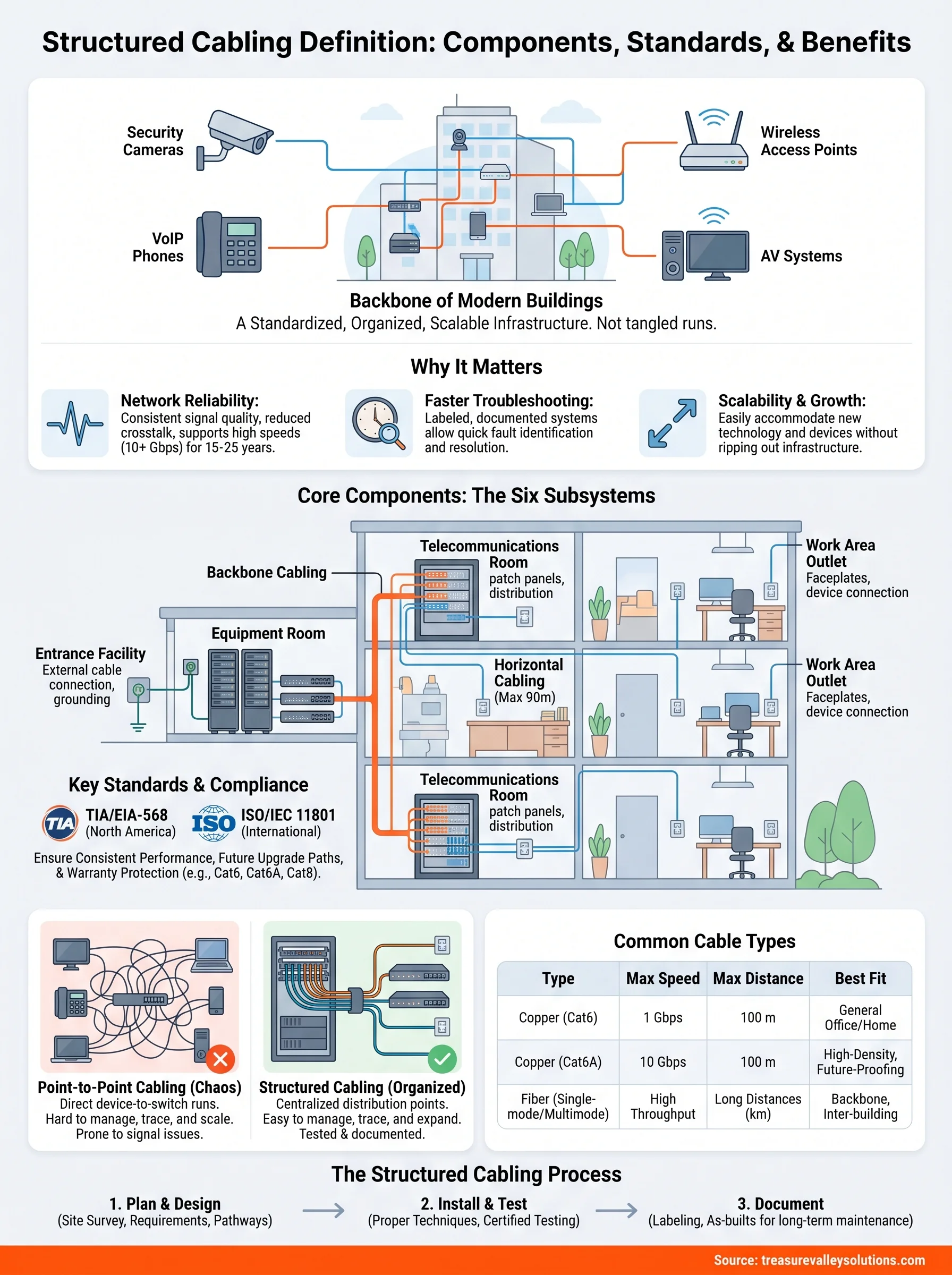
Structured Cabling Definition: Components, Standards, Uses
Every network-connected device in a building, security cameras, VoIP phones, wireless access points, AV systems, depends on physical cabling to function. When that cabling is installed without a plan, you end up with tangled runs, signal issues, and expensive troubleshooting. A clear structured cabling definition helps you understand the alternative: a standardized infrastructure designed to keep everything organized, reliable, and ready to scale.
Structured cabling is the backbone of modern buildings, whether it's a home wired for smart technology or a commercial facility supporting hundreds of devices. It follows established industry standards from organizations like TIA and EIA, which govern everything from cable types to how termination points are organized. Understanding these standards matters because they directly affect network performance, future upgrade paths, and long-term maintenance costs.
At Treasure Valley Solutions, we design and install integrated technology systems for homes and businesses across the Boise and Meridian area, and structured cabling is the foundation of every project we take on. From pre-wiring new construction to retrofitting existing buildings with smart home and commercial AV systems, we see firsthand how proper cabling infrastructure determines whether a system runs smoothly or becomes a headache. This article breaks down the full definition of structured cabling, walks through its core components and standards, and explains why it matters for anyone planning a technology installation.
Why structured cabling matters
Most people only think about cabling when something stops working. A dropped video call, a security camera that keeps going offline, a Wi-Fi dead zone in a room that should have full coverage, these problems often trace back to poor cable infrastructure, not the devices themselves. Understanding the structured cabling definition is not just a technical exercise; it directly affects how well every connected system in your building performs from day one.
Network reliability starts at the physical layer
Your network is only as stable as the cables carrying its signals. When cabling is installed without a structured plan, you get inconsistent signal quality, crosstalk between cable runs, and terminations that degrade over time. Structured cabling eliminates most of these problems by standardizing how cables are routed, terminated, and tested before any devices go live.
A properly installed structured cabling system can support network speeds above 10 Gbps and carry that performance reliably for 15 to 25 years, which makes the upfront investment straightforward to justify.
Poor physical infrastructure limits the performance ceiling of everything above it. Even if you install enterprise-grade switches and the fastest routers available, unorganized or low-quality cabling acts as a bottleneck that degrades throughput, increases latency, and causes intermittent failures that are difficult to diagnose.
Troubleshooting becomes faster and cheaper
When a technician walks into a server room or telecommunications closet and finds an unorganized mass of unlabeled cables, diagnosis takes significantly longer. Every extra hour of troubleshooting translates directly into cost, whether that's billable labor or downtime affecting your operations. Structured cabling systems use consistent labeling, color coding, and documentation so any trained technician can trace a cable run, identify a fault, and resolve it quickly.
For commercial facilities in particular, downtime has a real financial impact. Retail environments, office buildings, restaurants with point-of-sale systems, and schools relying on AV infrastructure all depend on network uptime. A structured system reduces the time between "something is wrong" and "the problem is fixed."
Scalability without starting over
Technology needs change. You might add a wing to your office, upgrade your security camera system, or install new wireless access points to handle more devices. A structured cabling system is designed to accommodate growth without requiring you to rip out existing infrastructure and start over. Because every run is documented and every termination point is organized, adding new drops or repurposing existing ones is a manageable task rather than a project.
This matters especially for businesses that plan to expand, residential builders who want homes to be move-in ready for smart technology, and property managers who need consistent infrastructure across multiple units. Structured cabling gives you a platform that adapts as your needs evolve, rather than a tangle of cables that has to be replaced every time your requirements shift.
Compliance and warranty protection
Industry standards like those published by the Telecommunications Industry Association set specific requirements for how cabling systems must be installed and tested. Meeting these standards is not just a formality. Many cable and hardware manufacturers tie their warranties directly to standard-compliant installations. If your cabling does not meet TIA or ISO specifications, you may void the warranty on expensive networking equipment before it ever has a chance to fail on its own.
Compliance also matters if your building undergoes inspection or if you lease space to tenants who require certified infrastructure. Documented, standards-compliant cabling protects your investment and gives you leverage in those conversations.
The formal definition and key terms
The structured cabling definition used across the industry comes from standards bodies rather than individual manufacturers, which keeps the language consistent regardless of which vendor's hardware you use. At its core, structured cabling refers to a complete system of cabling and associated hardware that provides a comprehensive telecommunications infrastructure. This infrastructure serves a building or campus and supports multiple hardware uses, from data networking and voice to building automation and security systems, all through a single, organized physical layer.
What the standards say
According to the Telecommunications Industry Association, structured cabling describes an infrastructure built around a standardized architecture, one that organizes cabling into defined subsystems with specific roles. The key concept here is "standardized," because it means the system is designed to work the same way regardless of the active equipment connected to it. Your cabling infrastructure should remain independent of any single application so that you can swap out switches, routers, or other active devices without redesigning the physical layer underneath.
A structured cabling system is not tied to any specific network technology, which means it can carry Ethernet, voice, video, and building management signals across the same organized infrastructure.
Key terms you will encounter
Before you work through a structured cabling plan or review a proposal from an installer, you need to recognize the terms that appear repeatedly. Each one refers to a specific, measurable concept within the broader system rather than a vague description.
| Term | What it means |
|---|---|
| Horizontal cabling | Cable runs from a telecommunications room to individual work area outlets |
| Backbone cabling | Cabling that connects telecommunications rooms, equipment rooms, and entrance facilities |
| Work area outlet | The termination point at the end-user location where devices plug in |
| Patch panel | A mounted hardware assembly that organizes and terminates cable runs in a central location |
| Channel | The complete end-to-end transmission path from equipment to equipment, including all connectors and cables |
| Permanent link | The portion of a channel that excludes the equipment cords at each end |
Knowing these terms lets you read documentation accurately and ask precise questions during an installation or review. When you see them in a proposal or a testing report, they point to specific parts of your infrastructure, giving you a reliable way to verify that the work meets the performance specifications your systems actually require.
The six subsystems and core components
Any complete structured cabling definition includes a breakdown of six subsystems that together form the physical infrastructure of a building's telecommunications network. Each subsystem handles a specific function, and all six must work together for the system to deliver consistent, reliable performance. Understanding what each subsystem does helps you evaluate whether a proposed installation covers everything your building needs.
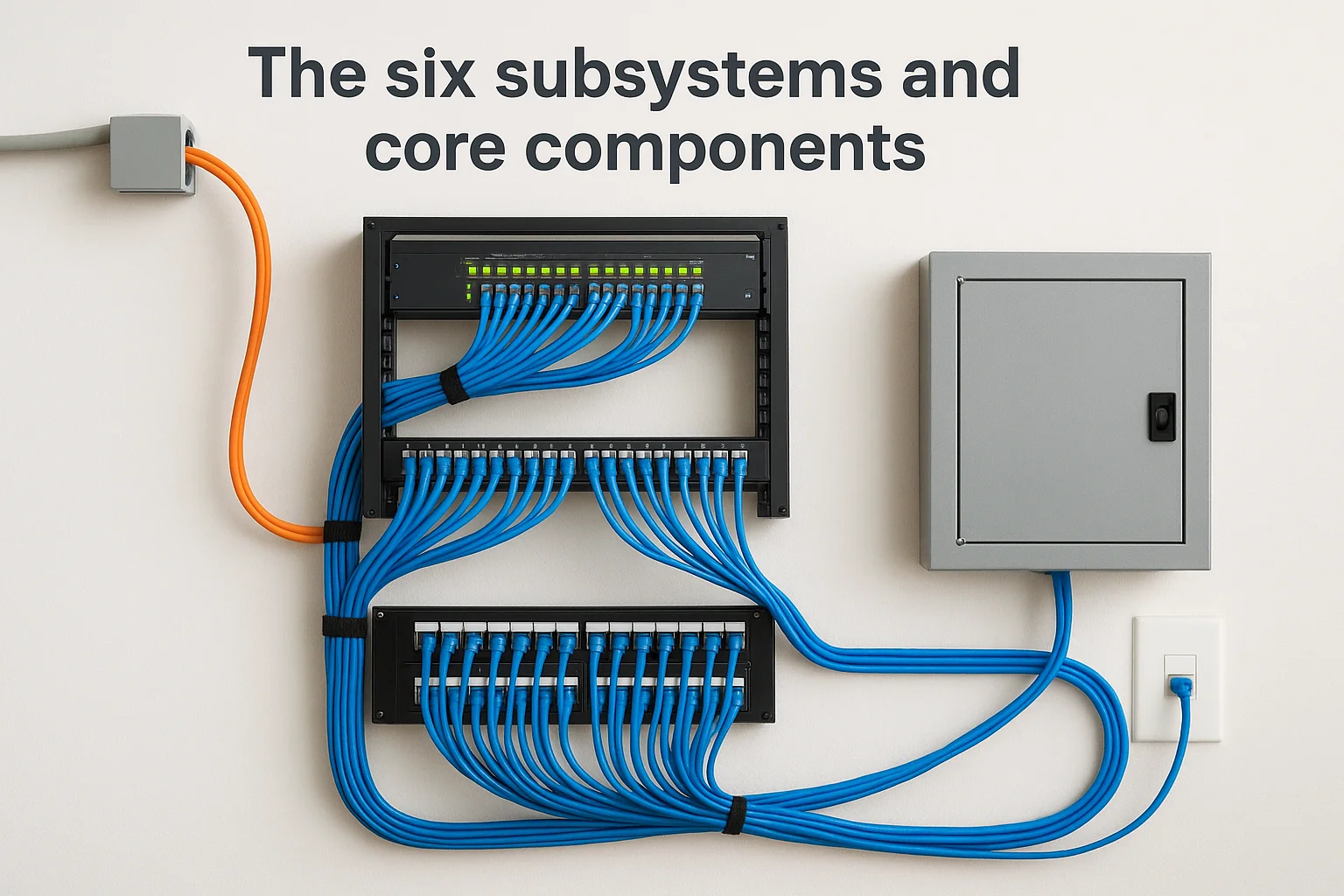
The building-level subsystems
The first three subsystems deal with how signal enters your building and how it moves between spaces at a larger scale. The entrance facility is where external cabling from a service provider connects to your internal infrastructure, where outside plant cables transition to inside plant cables, and where grounding and protection hardware guards against electrical interference.
If your entrance facility is not properly protected and grounded, every subsystem downstream is at risk from power surges and signal interference.
Your equipment room houses the active gear that drives your network, including servers, switches, and telephony hardware. Unlike a telecommunications room, which serves as a distribution point, the equipment room is where primary network processing happens. Backbone cabling connects the entrance facility, equipment room, and any telecommunications rooms across floors or buildings, carrying aggregated traffic between those distribution points.
The user-facing subsystems
These final three subsystems bring connectivity from distribution points directly to the devices using your network. The telecommunications room, sometimes called a telecom closet, sits on each floor or zone and holds patch panels, switches, and cable management hardware. It terminates horizontal runs and connects them back to the backbone.
Horizontal cabling runs from the telecommunications room out to each individual work area outlet, and it represents the largest volume of cable in most installations. TIA standards cap horizontal permanent links at 90 meters, a limit that directly shapes how you position telecom rooms relative to work areas. Finally, the work area covers the outlet, faceplate, and short equipment cord that plugs a device into the network. Every endpoint in your building, whether an IP camera, a VoIP phone, or a wireless access point, connects through this subsystem.
Standards and compliance you will hear about
Any complete structured cabling definition includes references to industry standards, and you will hear specific names repeated throughout any professional installation conversation. These standards exist because cabling infrastructure has to perform consistently across thousands of different buildings, device types, and network configurations. Knowing which standards apply to your project helps you verify that a proposed system is built to perform at the level your applications actually require, not just to the minimum that looks acceptable during installation.
TIA/EIA standards for North America
The Telecommunications Industry Association and the Electronic Industries Alliance jointly developed the foundational standards that govern most commercial and residential structured cabling installations in the United States. The TIA-568 series is the most referenced set, covering everything from cable specifications and connector types to testing requirements and channel performance limits. When an installer tells you a system is "TIA-568 compliant," they mean the installation follows these documented requirements for how cables are routed, terminated, and verified.
Specifying TIA-568 compliance in your installation agreement is one of the simplest ways to protect your investment, because it ties the work to a measurable, documented standard rather than a subjective assessment of quality.
TIA standards also define performance categories for cables and channels, which is where terms like Cat6, Cat6A, and Cat8 originate. Each category specifies the frequency range and transmission characteristics the cabling must support, so you can match your cable choice to your actual bandwidth and distance requirements.
ISO/IEC 11801 for international projects
If your organization operates across multiple countries or works with vendors and systems specified internationally, you will encounter ISO/IEC 11801, which is the international equivalent of the TIA-568 framework. The two standards align closely in most technical requirements but use slightly different terminology for categories and classes. ISO/IEC 11801 uses "Class" designations rather than category numbers, so Class EA corresponds roughly to Cat6A under TIA.
Understanding both frameworks matters if you review documentation from international equipment manufacturers or if your building is designed by a firm that specifies to international standards. In practice, a system that meets TIA-568 requirements will typically satisfy ISO/IEC 11801 requirements for the same performance tier, but confirming that alignment before installation prevents compliance gaps later.
Structured vs point-to-point cabling
Understanding the structured cabling definition becomes much clearer when you compare it directly to the alternative: point-to-point cabling. Point-to-point wiring connects each device directly to its destination, one cable per connection, with no centralized termination or distribution point in between. Many small installations start this way because it looks simpler upfront, but the approach creates serious problems as the number of devices grows.
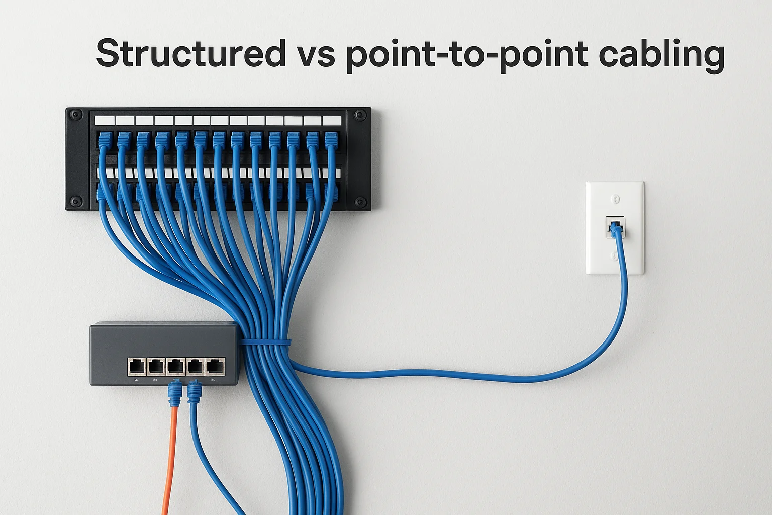
How point-to-point cabling works
With point-to-point cabling, every device gets its own dedicated cable run straight to the router, switch, or panel it needs to reach. There is no patch panel, no labeled distribution point, and no standardized termination method governing how the work is done. This approach works when you have a handful of devices in a small, contained space.
Once a point-to-point system grows beyond a dozen devices, troubleshooting a single fault often requires tracing unlabeled cables across walls, ceilings, and closets before you can identify the source.
Each new device you add creates another unmanaged run, and the cumulative result is a system that becomes progressively harder to document and maintain. Signal quality also suffers because point-to-point runs rarely account for interference from adjacent cables, bend radius limits, or the distance restrictions that structured systems enforce by design.
Where structured cabling outperforms point-to-point
Structured cabling centralizes all terminations at defined distribution points, which means any cable run can be traced, tested, and documented from a single location. When you need to move a workstation, add a security camera, or reconfigure a zone, you make a change at the patch panel rather than pulling a new cable through a finished wall. This keeps your infrastructure flexible without becoming fragile as your needs change over time.
The performance difference also shows up in measurable results. Structured systems are tested against specific channel performance benchmarks before they go live, so you know what bandwidth and latency to expect from day one. Point-to-point installations typically skip formal testing, which means you discover performance problems only after devices are already deployed and actively failing.
| Factor | Point-to-point | Structured cabling |
|---|---|---|
| Scalability | Low | High |
| Troubleshooting speed | Slow | Fast |
| Formal testing | Rarely done | Required |
| Long-term cost | Higher | Lower |
Common cable types and where they fit
Any working structured cabling definition accounts for the fact that different applications require different physical media. The cable type you choose directly affects bandwidth capacity, maximum run length, and cost per drop, so matching the right cable to the right use case is one of the most important decisions in any cabling project.
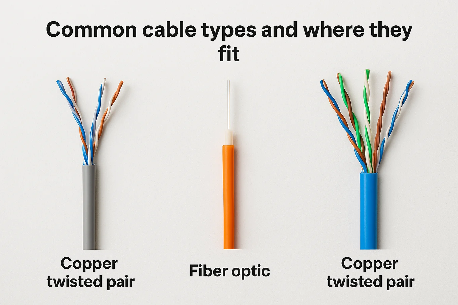
Copper twisted pair categories
Copper twisted pair cable is the most common choice for horizontal runs that terminate at workstations, cameras, access points, and phones. Category 6 (Cat6) supports 1 Gbps at runs up to 100 meters and handles the majority of general-purpose networking applications in both residential and commercial buildings. If your installation requires 10 Gbps to the workstation, Cat6A extends that performance across the full 100-meter channel by using a tighter twist rate and additional shielding to reduce crosstalk.
Specifying Cat6A for new construction costs more upfront but eliminates the need to recable when your network equipment upgrades to 10 Gbps speeds.
Cat8 exists for very short, high-density runs inside data centers where speeds up to 40 Gbps are required over distances under 30 meters. It rarely makes sense in standard office or residential builds, where Cat6A covers virtually every performance requirement you are likely to encounter.
| Cable type | Max speed | Max distance | Best fit |
|---|---|---|---|
| Cat6 | 1 Gbps | 100 m | Offices, homes, general AV |
| Cat6A | 10 Gbps | 100 m | High-density commercial, future-proofing |
| Cat8 | 40 Gbps | 30 m | Data center, server-to-switch links |
Fiber optic cable and when to use it
Fiber optic cable carries light signals instead of electrical ones, which gives it two practical advantages over copper: immunity to electromagnetic interference and the ability to cover much longer distances without signal degradation. Single-mode fiber supports runs measured in kilometers, making it the standard choice for backbone cabling between buildings or between widely spaced telecommunications rooms.
Multimode fiber works for shorter backbone runs inside a single building and costs less than single-mode while still delivering high throughput across distances that copper cannot handle reliably. For most commercial projects, you will use fiber for vertical and inter-building backbone runs while copper handles every horizontal drop to end-user devices.
How to plan and design a structured cabling system
Planning a structured cabling system before a single cable gets pulled is the step that separates installations that perform well for decades from ones that need expensive rework within a few years. A solid design accounts for current needs and future growth, so you are not limited by the decisions made during initial construction. Every element in the broader structured cabling definition, from subsystem layouts to cable categories, should be decided on paper before any physical work begins.
Start with a site survey
Your first task is to walk the building and collect the information that drives every other decision in the design process. Document the floor plan accurately, note where walls, ceilings, conduit runs, and existing infrastructure are located, and identify any obstacles that affect cable routing. You also need to catalog every location where a device will connect, including workstations, security cameras, wireless access points, AV panels, and IP phones.
Skipping the site survey and designing from a floor plan alone leads to cable runs that cannot physically be installed as drawn, which forces costly on-the-fly changes during installation.
Define your performance requirements
Once you know what the building contains, you need to match cable categories and fiber types to the actual performance demands of your systems. A general office environment running standard Ethernet and VoIP usually works well with Cat6, while installations that will support 10 Gbps workstation speeds or high-bandwidth AV distribution need Cat6A at minimum. Define these requirements in writing before you purchase materials so your specification drives your budget rather than the other way around.
Your performance requirements also determine how you size the active equipment. Switch port counts, power-over-Ethernet budgets, and uplink speeds all depend on how many drops you are running and what those drops will carry. Locking this in during the design phase prevents situations where your cabling is ready but the hardware cannot support what you have installed.
Map your distribution points and cable paths
With device locations and performance specs confirmed, you can position telecommunications rooms and equipment rooms to keep horizontal runs within the 90-meter permanent link limit required by TIA-568. Plan your backbone routes between distribution points next, choosing fiber for inter-floor or inter-building runs and copper where distances are short. A complete cable pathway map, showing exact routes through conduit, cable trays, and wall penetrations, gives your installation team a clear guide and becomes part of your permanent system documentation.
Installation, testing, and documentation basics
Every structured cabling definition you will read covers the theory, but the physical installation is where that theory either holds up or falls apart. Proper installation technique determines whether your system delivers the performance the design promised, and cutting corners during this phase creates problems that compound over time. Rough handling, missing labels, or skipped tests leave you with an infrastructure that looks complete but fails under real operating conditions.
Pull, terminate, and dress cables properly
Cable installation technique affects signal quality in ways that testing equipment will catch even if your eyes cannot. You must maintain the correct bend radius throughout every run, avoid pulling cables past their maximum tension rating, and keep jacket damage from happening when cables pass through conduit or framing. When you terminate copper at patch panels and outlets, untwist each pair only as far as the connector requires, because excessive untwisting raises crosstalk and degrades channel performance.
Cable dressing, the process of organizing and securing cables inside telecommunications rooms, directly affects your ability to manage the system later. Neat bundling, consistent routing paths, and proper strain relief at every termination point keep the infrastructure manageable as you add or reconfigure drops over time.
Test every link before devices go live
Testing is not optional, and it is not something you run after devices are already connected and complaints come in. A qualified installer tests each permanent link and channel using a calibrated field tester that verifies the run against the TIA-568 performance specification you designed to. Parameters like insertion loss, return loss, and near-end crosstalk all have defined pass/fail thresholds for each cable category, and any link that fails those thresholds gets corrected before the job is signed off.
Keeping the test reports from every link gives you proof of performance at installation, which protects you if a network problem surfaces months later and someone questions whether the cabling is the cause.
Document the system completely
Documentation is the part of the installation that keeps paying off long after the cables are pulled. Label every cable, outlet, patch panel port, and telecommunications room with a consistent naming scheme, and record those labels in a physical or digital as-built drawing that reflects exactly what was installed, not what was originally designed. Your technician, or anyone who works on the system in the future, should be able to pick up that documentation and locate any run or termination point in minutes without guessing.
Next steps
A complete structured cabling definition covers far more than cable types and connector standards. It describes a systematic approach to physical infrastructure that determines how every device in your building connects, performs, and scales over time. Whether you are planning a new construction project, retrofitting an existing building, or upgrading an aging network, the decisions you make about cabling lay the foundation for everything that runs on top of it. Proper design, installation, and documentation are not optional extras; they are the difference between infrastructure that serves you for 20 years and one that requires costly rework within five.
Treasure Valley Solutions designs and installs structured cabling systems for homes and businesses across the Boise and Meridian area. Every project starts with a site survey and a design built around your actual requirements, not a generic template. If you are ready to build infrastructure that performs reliably for years to come, contact our team to talk through what your project needs.