
A home golf simulator is only as good as the wiring behind it. You can spend thousands on a premium launch monitor, projector, and impact screen, but if your golf simulator wiring setup isn't planned...
Golf Simulator Wiring Setup: Power, HDMI, And Cable Plan
A home golf simulator is only as good as the wiring behind it. You can spend thousands on a premium launch monitor, projector, and impact screen, but if your golf simulator wiring setup isn't planned correctly, you'll deal with signal drops, tripped breakers, and a tangle of cables running across the floor. Getting the electrical and connectivity side right from the start saves you from headaches (and costly rework) down the road.
This guide breaks down everything you need to plan: dedicated circuits and outlet placement, proper HDMI and data cable routing, and strategies to keep the whole setup clean and organized. Whether you're converting a garage, basement, or spare room, you'll walk away with a clear wiring plan you can act on.
At Treasure Valley Solutions, we design and install custom AV and technology systems across the Boise and Meridian area, including dedicated entertainment spaces like golf simulator rooms. We've seen firsthand what works (and what causes problems), so this guide reflects real installation experience, not guesswork.
What you need before you run any wires
Before you touch a cable or drill a single hole, you need a clear inventory of every device in your simulator and what each one demands from your electrical system. A proper golf simulator wiring setup starts on paper, not on the wall. Skipping this planning step is the most common reason people end up with overloaded circuits, insufficient outlets, and cables that don't reach their destinations.
Know your components and their power draw
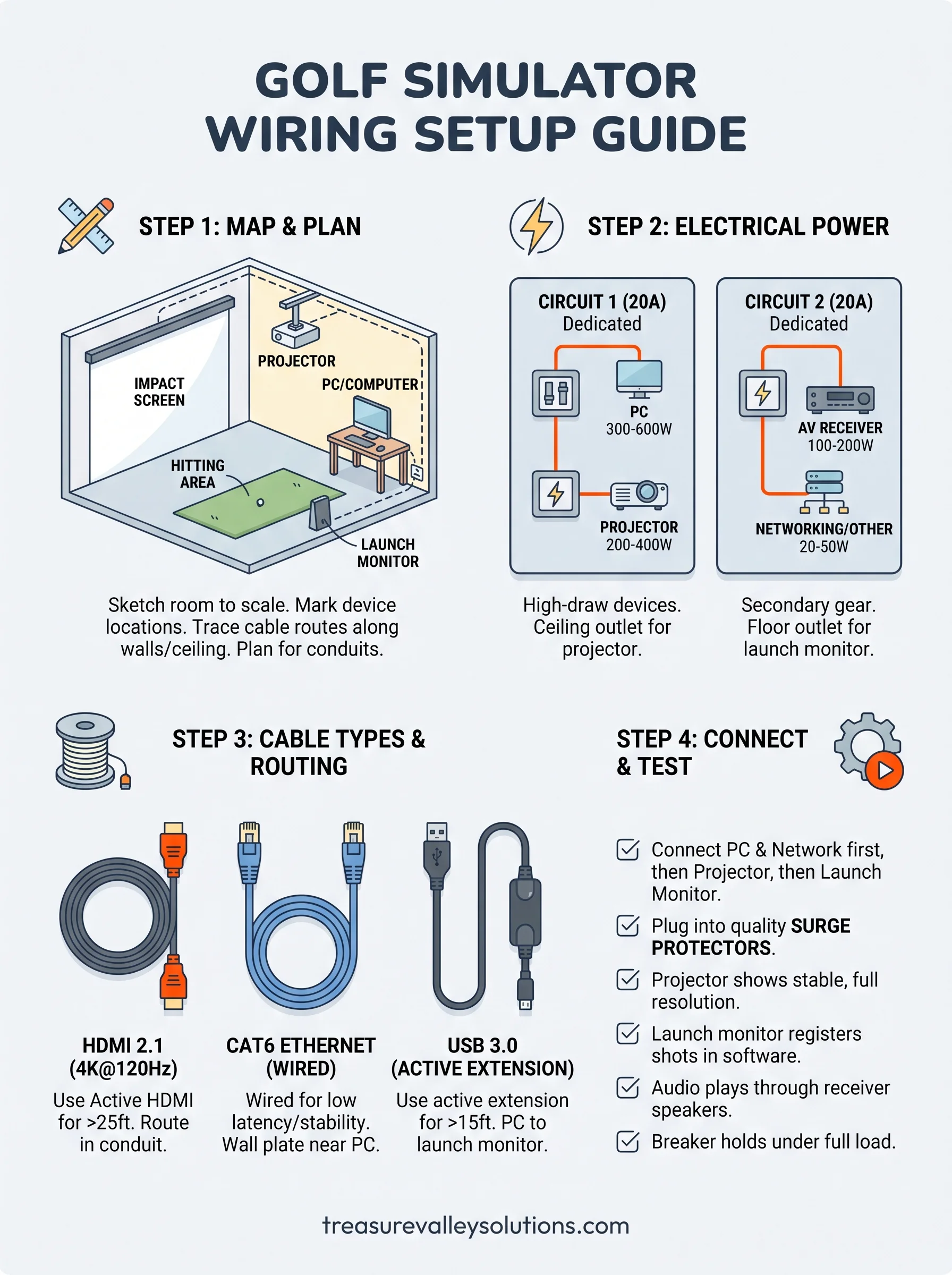
Your simulator room will typically run four to six powered devices at the same time: a gaming PC or simulator computer, a projector or short-throw laser projector, a launch monitor, a receiver or amplifier, and possibly a secondary display. Each of these has a specific wattage draw you need to account for before planning circuits. Knowing the total load upfront tells you how many dedicated circuits you need and where to position outlets.
Total up every device's wattage before calling an electrician. A single 15-amp circuit at 120V supports roughly 1,440 watts, and most simulator setups draw more than that across all devices combined.
Here's a quick reference for typical loads:
| Device | Typical Wattage |
|---|---|
| Gaming PC | 300-600W |
| Projector | 200-400W |
| Launch monitor | 10-30W |
| AV receiver | 100-200W |
| Networking gear | 20-50W |
Tools and materials to gather first
Having the right tools on hand before you start saves multiple trips and keeps the project moving. You'll need a stud finder, a drill with long bits, a fish tape or wire fishing rod, cable staples, and a label maker. For materials, plan your cable runs in advance so you buy the correct cable lengths and types: HDMI 2.0 or 2.1 for video, Cat6 for networking, and USB extension cables if your launch monitor sits far from the PC.
Pull these items together before day one:
- Stud finder and laser level
- 3/4-inch drill bit for wall penetrations
- Fish tape (at least 25 feet)
- Cable raceways or conduit sections
- Velcro cable ties (avoid zip ties, which can pinch and damage cable jackets)
- Permanent marker and label tape
Step 1. Map the room and pick device locations
Before you plan any cable runs, you need to know exactly where each device will sit. This is the foundation of a clean golf simulator wiring setup, and it determines outlet locations, cable lengths, and where you'll route conduit or raceways.
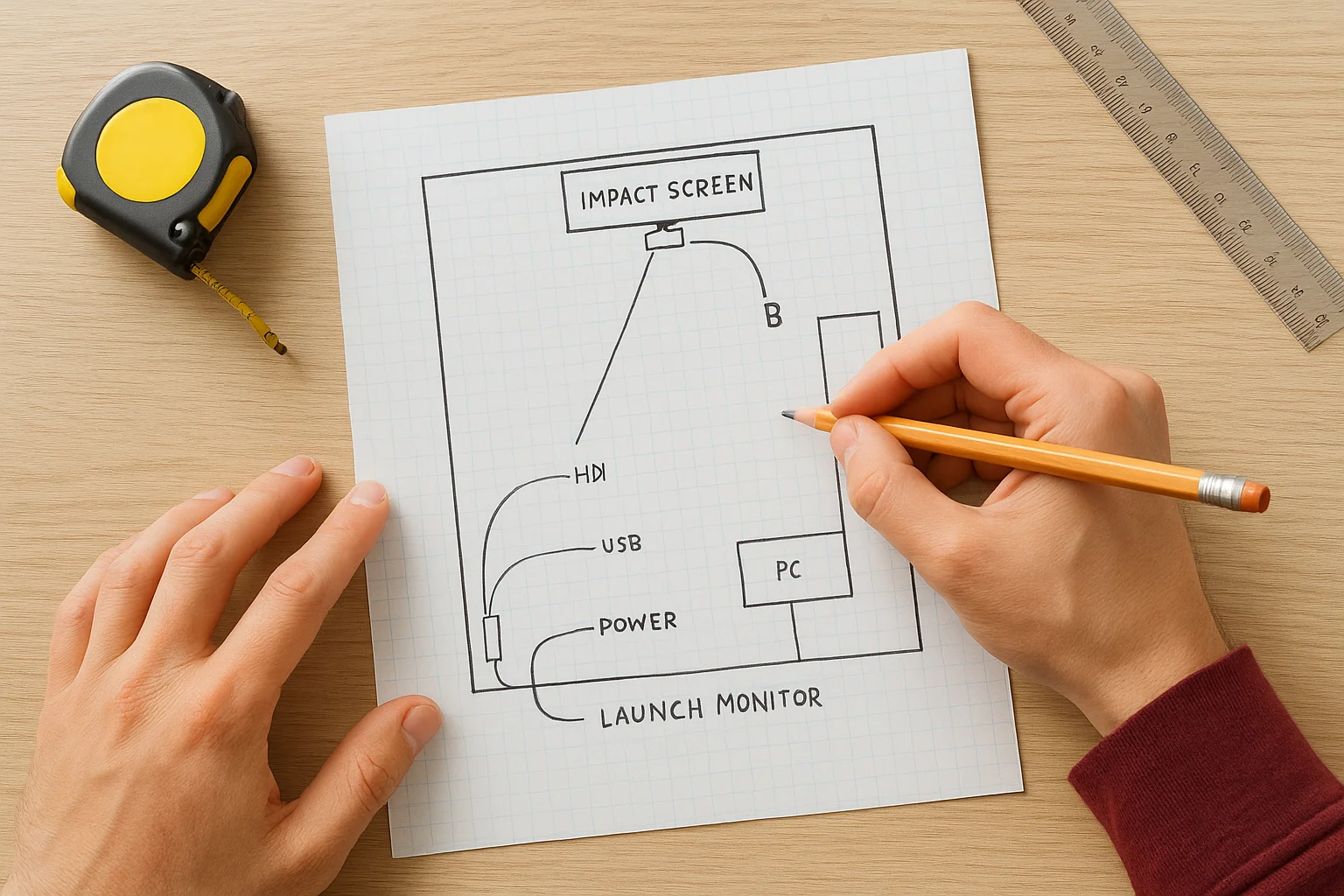
Sketch a floor plan with device zones
Grab a tape measure and sketch your room to scale on paper or in a free tool like Google Drawings. Mark the impact screen wall first, since that anchors everything else. Your projector mounts to the ceiling behind the hitting position, the PC typically sits to one side on a shelf or cabinet, and the launch monitor sits at floor level near the hitting mat.
Place your launch monitor and PC as close together as possible to minimize USB cable length, since most USB signals degrade past 15 feet without an active extension.
Mark cable paths before drilling
Once you've placed each device on your sketch, draw lines showing where HDMI, USB, and power cables will travel. Trace paths along wall edges and ceiling joists to keep cables hidden and protected. Flag every location where a cable needs to pass through a wall or ceiling with a note on your sketch, so you drill in the right spots the first time and avoid rework.
Step 2. Plan electrical power and outlet placement
Once you have your device map complete, power planning is your next critical task. A well-planned golf simulator wiring setup requires at least two dedicated 20-amp circuits: one for the PC and projector, and one for the AV receiver and any other high-draw gear. Running everything on a single shared circuit is the fastest way to trip a breaker mid-round.
Dedicate circuits for high-draw devices
Your PC and projector together can pull 600-1,000 watts under load, which pushes a standard 15-amp circuit to its safe limit on its own. Hire a licensed electrician to install dedicated 20-amp circuits before your walls close up, since retrofitting circuits later means opening drywall again. Each circuit should feed a dedicated outlet cluster near each device zone: one cluster at the projector ceiling mount and one at the PC and AV equipment area.
Run a minimum of two 20-amp circuits for any serious simulator room build. One circuit for display and projection, one for compute and audio.
Position outlets before walls close up
New construction or an open-stud remodel gives you the best opportunity to place outlets exactly where you need them. Put a ceiling outlet box at the projector mount location to eliminate cord drops. Floor-level outlets near the hitting mat handle the launch monitor and any secondary gear cleanly, keeping cables short and out of the swing path.
Step 3. Run HDMI, Ethernet, and USB the right way
With power sorted, your data and video cables deserve just as much planning. A poor HDMI run or an undersized USB cable causes signal loss and input lag, both of which break the simulator experience mid-round. Treating these cable runs as a core part of your golf simulator wiring setup keeps performance reliable and the room looking clean.
Choose the right cable for each connection
HDMI 2.1 cables handle 4K at 120Hz without signal degradation, making them the correct choice for any projector run over 10 feet. For runs longer than 25 feet, use an active HDMI cable rather than a passive one, since passive cables drop signal integrity at longer distances. Route HDMI through in-wall conduit or a ceiling raceway so you can swap it out later without cutting drywall.
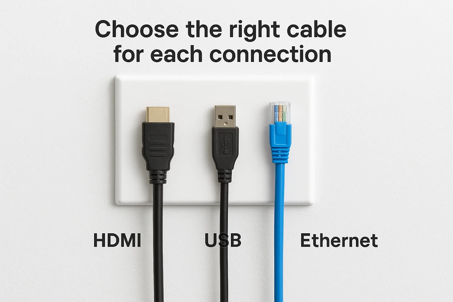
For USB runs longer than 15 feet between your PC and launch monitor, use an active USB 3.0 extension cable to maintain a stable data connection.
Keep Ethernet in the plan
A wired Ethernet connection to your simulator PC eliminates the latency and drop-outs that Wi-Fi introduces during online play or software updates. Run Cat6 cable from your router or network switch to a wall plate near the PC station. This gives you a clean, permanent connection that stays consistent regardless of how many other devices share your network.
Step 4. Connect, configure, and test the full system
With your power and cables in place, connecting everything in the correct order prevents confusion and makes troubleshooting easier if something doesn't work on the first try. Your golf simulator wiring setup is only complete once every device communicates correctly and the system runs a full session without dropping signal or tripping a breaker.
Connect devices in the right order
Start by powering on your networking gear and PC first, then bring up the projector, and finally connect the launch monitor via USB. This sequence lets the operating system recognize each peripheral before you open your simulator software. Plug everything into a quality surge protector on each dedicated circuit rather than directly into the wall outlet to protect your gear from voltage spikes.
Label each cable at both ends before you close up raceways, so any future troubleshooting takes minutes instead of an afternoon.
Test every signal path before finishing
Run your simulator software through a complete hole to confirm the launch monitor captures shots, the projector displays a clean image without lag, and audio plays through your receiver. Check each HDMI and USB connection by tugging each cable lightly at both ends to confirm it seats firmly.
Use this quick checklist before calling the installation done:
- Projector displays full resolution without flicker
- Launch monitor registers every shot in the simulator software
- Audio plays through all speakers at correct volume
- Wired network connection shows stable throughout gameplay
- Breaker holds steady under full device load
Next steps to keep it clean and reliable
Your golf simulator wiring setup doesn't end at the first test round. Over time, cables shift, firmware updates change device behavior, and new components get added to the room. Schedule a quick check every six months: tug each cable connection, verify that your breaker holds under full load, and confirm your simulator software still recognizes the launch monitor on startup. Catching a loose HDMI connection or a fraying USB cable early costs you nothing; ignoring it costs you a failed session or a damaged device.
Beyond routine checks, document your entire setup in a simple notes file: cable lengths, circuit assignments, device firmware versions, and outlet locations. That reference saves you significant time if you ever need to swap a projector or add a speaker to the room. If you want a professional team to handle the design and installation from the start, see examples of our completed AV projects to get a sense of what a clean, custom build looks like.