 (208) 991-3502
 Meridian, ID




A golf simulator is only as good as the infrastructure behind the walls. Before you hang a screen or mount a launch monitor, you need to get your low voltage golf simulator wiring right. That means pl...
A golf simulator is only as good as the infrastructure behind the walls. Before you hang a screen or mount a launch monitor, you need to get your low voltage golf simulator wiring right. That means planning cable runs for HDMI, Ethernet, power outlets, and conduit, all before the drywall goes up. Skip this step or cut corners, and you'll end up tearing into finished walls later, spending more time and money than the simulator itself.
At Treasure Valley Solutions, we prewire rooms across the Boise and Meridian area for home theaters, media rooms, and yes, golf simulator builds. We've seen firsthand what happens when wiring is an afterthought. This guide breaks down exactly what cables, locations, and infrastructure you need to plan for, whether you're working with a builder on new construction or retrofitting a basement or garage.
Think of this as your prewire checklist, a room-by-room, cable-by-cable reference so nothing gets missed. We'll cover signal cables, networking, power placement, conduit strategy, and a few details most people don't think about until it's too late. By the end, you'll have a clear plan to hand your electrician, your builder, or your installer so the actual simulator setup goes smoothly.
What to plan before you pull wire
Before you touch a cable, you need to understand what your room demands. Low voltage golf simulator wiring decisions depend on where your screen, projector, launch monitor, and PC will live. Getting these positions locked in early is the single most important step, because every cable run flows from those anchor points.
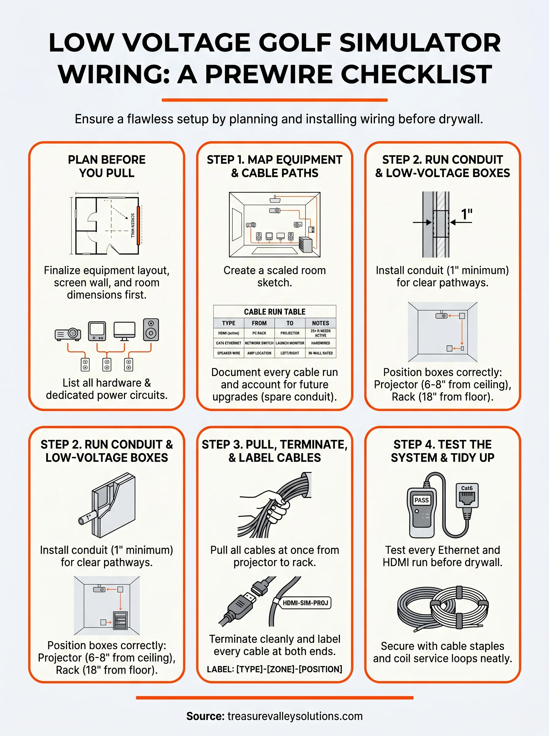
Finalize your equipment layout on paper before you measure a single cable run. Changes after wiring is roughed in cost time and money.
Room dimensions and screen wall position
Your room dimensions control everything from cable lengths to outlet placement. A standard simulator bay needs at least 10 feet of ceiling height and roughly 15 to 20 feet of depth, but those numbers shift based on the launch monitor you choose and the screen size you plan to hang. Mark the exact center of your screen wall on your floor plan before anything else, because your projector mount, HDMI run, and audio drops all reference that point.
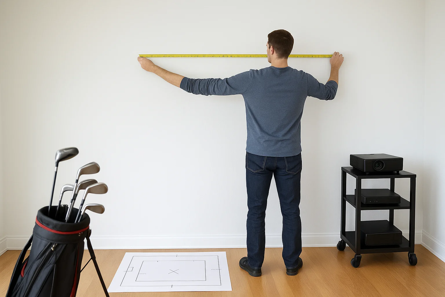
Measure from your projector mount location back to where your PC or media rack will sit. That distance sets your HDMI cable length, and anything over 25 feet typically needs an active HDMI cable or a fiber optic HDMI solution to maintain signal quality. Mark both endpoints on your plan so you can calculate conduit runs accurately.
Equipment list and power needs
Write out every piece of hardware that needs a connection before you set foot in the room with a drill. A typical setup includes a projector, a PC or gaming console, a launch monitor, a network switch, and speakers, and each of these needs either a low-voltage cable run, a dedicated power outlet, or both.
Your PC and projector need dedicated circuits positioned near their final install locations to avoid voltage drops or tripped breakers mid-round. Also note which devices need hardwired Ethernet drops versus Wi-Fi, because wiring your launch monitor and PC directly to a switch gives you more consistent performance than relying on a wireless signal.
Step 1. Map equipment and cable paths
Print or sketch your room to scale before you pull a single cable. Mark every piece of equipment on the drawing with its exact position: projector mount, screen wall, PC rack, launch monitor, and any speakers. This map becomes the reference document for every low voltage golf simulator wiring decision you make from here forward.
Create a cable run table
A cable run table turns your sketch into a working action plan. List every cable by type, start point, and end point, so you or your installer knows exactly what to pull and where it terminates.
Document your cable runs in writing before the walls close, or you'll be guessing at what's behind the drywall for every future change.
| Cable Type | From | To | Notes |
|---|---|---|---|
| HDMI (active) | PC rack | Projector mount | 25+ ft needs active cable |
| Cat6 Ethernet | Network switch | Launch monitor | Hardwired for reliability |
| Cat6 Ethernet | Network switch | PC rack | Dedicated drop |
| Speaker wire (16 AWG) | Amp location | Left/right speaker positions | In-wall rated jacket required |
Account for future upgrades
Leave at least one spare conduit run from your equipment rack location to the ceiling. If you add a second camera, a ceiling-mount speaker, or a second display later, that conduit saves you from cutting into finished walls. Label every conduit and cable end at rough-in so future changes take minutes, not hours.
Step 2. Run conduit and low-voltage boxes
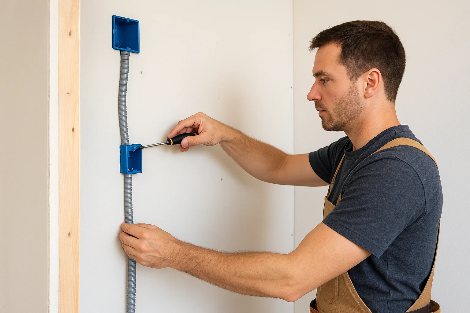
Once your cable map is finalized, start installing conduit and low-voltage boxes before any cables go in. Conduit protects your cables and gives you a clear pathway to pull new wires later without touching finished walls. For low voltage golf simulator wiring, a 1-inch EMT or flexible non-metallic conduit works well for most runs between your equipment rack and projector mount location.
Install conduit before drywall goes up, not after. Retrofitting conduit into finished walls costs far more time than doing it during rough-in.
Choose the right conduit size
Your conduit size determines how many cables you can pull through at once. A 1-inch conduit comfortably fits three to four cables, while a 1.5-inch run leaves room for future additions. Use flexible conduit sections at tight bends to avoid kinking cables during the pull. Here are the two most common conduit runs to plan:
- Projector mount to equipment rack: minimum 1-inch, 1.5-inch preferred
- Speaker drops from ceiling: half-inch conduit per speaker location
Position low-voltage boxes at the right height
Low-voltage brackets hold your cable terminations flush at the wall. Place projector-side boxes 6 to 8 inches from the ceiling so your HDMI and Ethernet drops land exactly where the projector mount attaches. Position rack-side boxes at 18 inches from the floor to align with standard AV rack heights, keeping cable slack manageable and the finished look clean.
Step 3. Pull, terminate, and label cables
With conduit in place and boxes set, you're ready to run your low voltage golf simulator wiring through the wall cavities. Pull all cables at the same time rather than one at a time, because bundling your runs together saves labor and reduces friction inside conduit. Feed cables from the projector end toward the equipment rack, leaving at least 18 inches of extra length at each termination point.
Never cut cables flush to the box during rough-in. Extra slack costs almost nothing now and saves you from a complete re-pull later.
Terminate cables cleanly at each end
Termination quality directly affects signal reliability. Seat HDMI connectors fully and check that each Cat6 jack follows the T568B wiring standard to avoid connection errors once equipment is powered on. For speaker wire, strip only half an inch of jacket and twist the conductors tightly before inserting them into binding posts or in-wall plates.
Label every cable at both ends
Label each cable at the wall box and at the rack the moment you finish the pull, before you forget which run is which. Use a simple format like the one below so anyone working on the room later can follow your layout instantly.
| Label Format | Example |
|---|---|
| [Cable Type]-[Zone]-[Position] | HDMI-SIM-PROJ |
| CAT6-SIM-LM | Ethernet drop for launch monitor |
| SPK-SIM-L | Left speaker wire run |
Step 4. Test the system and tidy up
Testing your low voltage golf simulator wiring before the walls close is the step most people skip, and it's the one that saves hours of troubleshooting later. Use a cable tester on every Ethernet run and verify each HDMI cable carries a signal end to end while you still have access to both termination points.
Test every cable before drywall goes up. A failed run you catch now costs a few minutes to fix; one you catch after finishing costs a full day.
Test each cable type systematically
Run a tone generator through every low-voltage cable to confirm there are no breaks or crossed pairs. For HDMI runs, connect a live source and display at both ends and verify full resolution before you consider the pull complete. Write a pass/fail result next to each line in your cable run table so you have a clear record of what was tested and when.
Secure and protect your work
Once all cables pass testing, secure any exposed runs with cable staples or clip-style fasteners rated for the cable type you used. Bundle cables neatly inside your equipment rack location using hook-and-loop ties rather than zip ties, which can crush cable jackets and degrade signal over time. Coil any service loops loosely and tuck them behind the low-voltage box before the drywall crew arrives.
Ready for a clean, reliable sim room
You now have a complete checklist to plan and execute your low voltage golf simulator wiring from start to finish. When you map your equipment layout first, install conduit before drywall, pull and label all cables at rough-in, and test everything before the walls close, you eliminate the most common and expensive mistakes simulator builders run into.
Every step in this guide exists to protect your investment and make future changes simple. A well-wired sim room gives you years of reliable performance with no mystery cables, no signal dropouts, and no tearing into finished walls when you upgrade your launch monitor or add a second display.
If you want a professional team to handle the prewire and installation for you, see examples of our completed projects and reach out to our team in Meridian to plan your build.
Need Expert Help?
Ready to implement these solutions in your own home or business?
Our Services
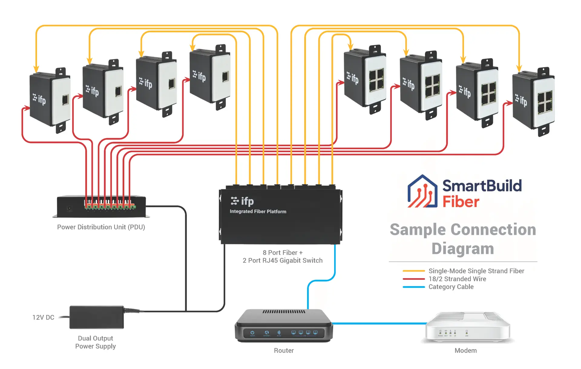
Future-proof fiber optic infrastructure.
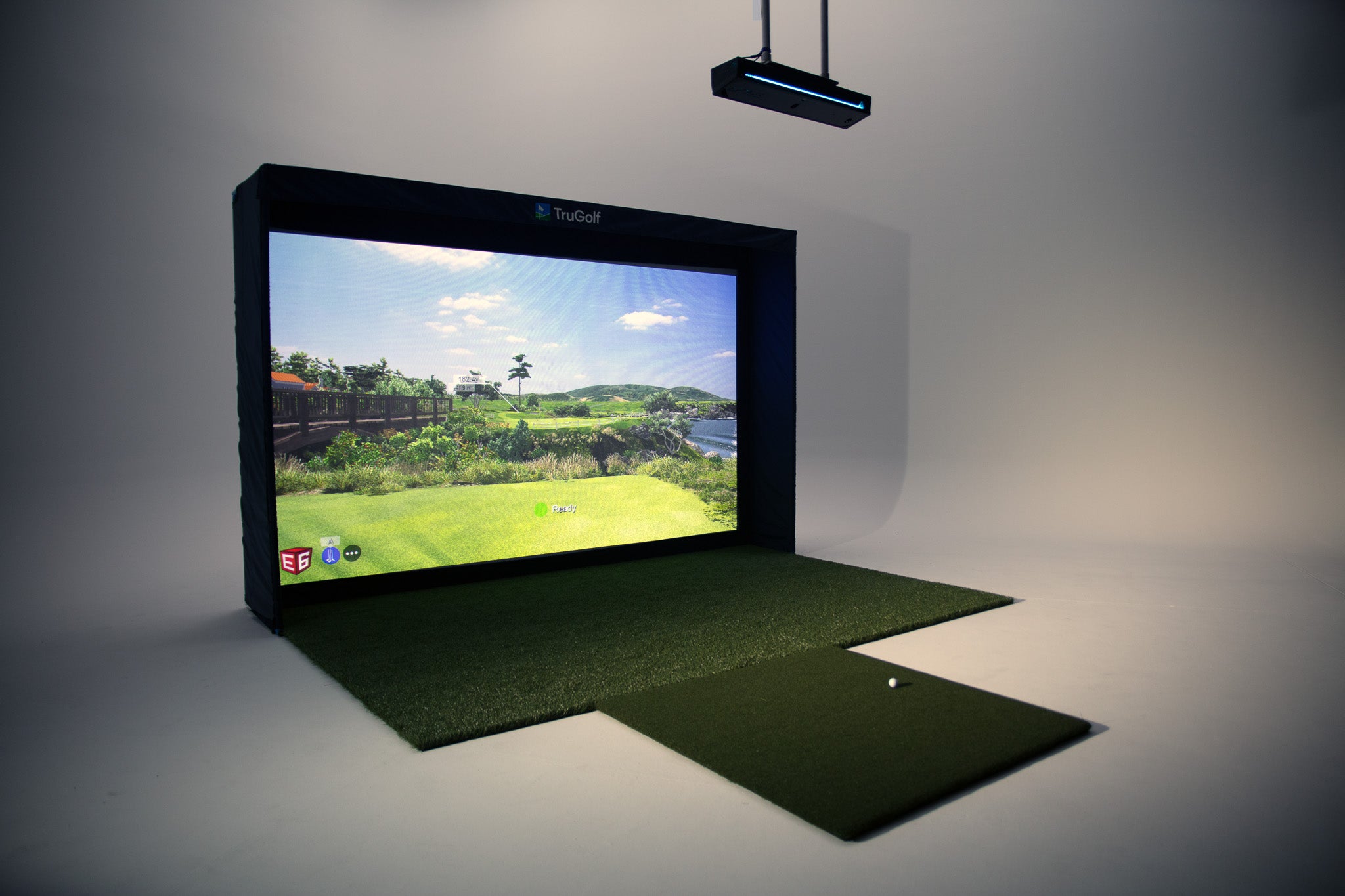
Room-first golf simulator planning, equipment coordination and AV installation for Treasure Valley homes, builders and venues.
Serving the Treasure Valley
Local installation in your city